The RS-232 serial protocol allows two devices to communicate over just a few wires. This page covers several serial cable designs that connect the NES to a PC via RS-232 serial.
RS-232 serial communication uses +12 and -12V signals, while the NES/Famicom consoles use +5V and 0V, commonly referred to as TTL. Connecting RS-232 directly would damage the console, so the levels must be translated to/from TTL. RS-232 is also inverted from normal, so a converter inverts the signals as well. Thus, a converter translates +12V to/from 0V, and -12V to/from +5V. There are a few ways to do this conversion, described below. There are also a few ways to connect the converted signals to the NES/Famicom consoles, described separately. A cable is a combination of a conversion method and connection method, so there are many different possibilities.
RS-232 signals are named TxD, RxD, CTS, and GND. Inverted TTL-level signals are named TX, RX, /CTS, GND, and +5V. The NES should never connect directly to any RS-232 signals, except GND.
The FTDI TTL-232R cable plugs into a USB port on almost any computer and provides the necessary TTL signals. This cable is by far the simplest to use and has high-quality drivers for modern operating systems (Windows, OS X, Linux). It is well-worth its cost. You'll also need a male header, 0.1 inch spacing, with 5 pins in a row (if more, you can cut off the extras). Cutting and stripping the wires is not recommended, because you might want to use the FTDI cable for other devices which have a header connector as well, like the popular Arduino microcontroller boards.
Do not connect the red or green wires to anything. Also, avoid the TTL-232R-3V3 cable which uses 3.3V signals and will not work with the NES.
      ___
     | _ |
 GND ||_|| Black
/CTS ||_|| Brown
     ||_|| Red
  TX ||_|| Orange
  RX ||_|| Yellow
     |'_'| Green
     |___|
 FTDI TTL-232R
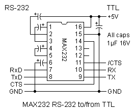
The MAX232 level converter chip internally generates the RS-232 +/-12V, ensuring compatibility with any serial port. Pay close attention to the counter-intuitive capacitor polarities.
| Quantity | Part | Comments |
|---|---|---|
| 1 | MAX232 | Could use variations, like MAX232A etc. See datasheet |
| 5 | 1 μF 16V or greater capacitor | Polarized electrolytic or tantalum |
GND     TxD   RxD
.-------------------.
\ 5   o   3   2   o /
 \                 /
  \ o   8   o   o /
   `-------------'
       CTS

9-pin RS-232 cable (female)
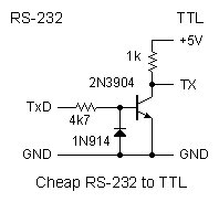
Two transistor-based inverters convert well enough to work with many current serial ports.
For a one-way PC to NES cable, construct an inverter that converts -12V to +5V and +12V to 0V (left-hand schematic). A diode prevents a -12V input from exceeding the transistor's reverse breakdown voltage (note diode's orientation).
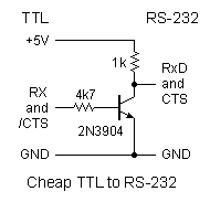
For a two-way cable that allows NES to PC as well, additionally construct a second inverter on the NES output (right-hand schematic). While this only goes down to 0V instead of -12V, it works with many modern serial ports.
| Quantity | Part | Comments |
|---|---|---|
| 2 | 2N3904 transistor | Any general-purpose NPN transistor will do, like the 2N2222, etc. |
| 2 | 1k resistor | 1/4 or 1/8 watt, brown-black-red |
| 2 | 4k7 resistor | 1/4 or 1/8 watt, yellow-violet-red |
| 1 | 1N914 diode | Other small-signal silicon diode will also work, like the 1N4148, etc. |
The TTL signals from one of the above circuits can be connected to the NES via a controller cable, or the NES/Famicom via the expansion port. For clarity, unused pins are not numbered or labeled.
The simplest method of connecting to a NES is through a normal controller cable. Colors are for standard NES controller cable, not third-party cables. Verify pin connections if possible.
              _
             /1| GND (brown)
(white) +5V |5.|
            |.3| RX and /CTS (orange)
            |.4| TX (yellow)
            '--'
      NES controller cable
The expansion port is the only way to connect on the Famicom. If desired, an external controller can still be connected at the same time as serial, as serial uses D4. A Neo-Geo controller extension cable can be used, as it has the same connector. A PC joystick connector will not work, due to having insufficient depth.
                   TX         GND
-----------------------------------
\  o   o   o   o   4   o   o   1  /
 \                               /
  \  15  o   o  12   o   o   o  /
   `---------------------------'
    +5V      RX & /CTS

Famicom female expansion cable (NOT YET VERIFIED)
Connecting to the expansion port avoids disruption of the second controller entirely, but connectors are hard to find.
          -------
         |  ___  |
     +5V | 1  48 | +5V
     GND | 2  47 | GND
         | [   ] |
         | [   ] |
         | [   ] |
         | [  43 | RX & /CTS
         | [   ] |
         | [   ] |
         | [   ] |
         | [   ] |
         | [   ] |
(back)   | [   ] |   (front of NES)
         | [   ] |
         | [   ] |
         | [   ] |
         | [   ] |
         | [   ] |
         | [   ] |
         | [   ] |
      TX | 20  ] |
         | [   ] |
         | [   ] |
         | [   ] |
         | [   ] |
         |  ---  |
          -------
NES expansion port on bottom of console
Contact Shay Green